Types of FSMs
There are two classifications of state machines based on the nature of their output generation:
- Moore: In this type, the outputs depend solely on the current state.
- Mealy: In contrast, this type generates one or more outputs that are influenced by both the current state and one or more inputs.
Beyond categorizing state machines by their output generation methods, they are also frequently classified based on the state encoding used. State encoding refers to how the different states of a state machine are represented in binary form.
- Binary: Each state is represented using standard binary numbers (e.g., 00, 01, 10, 11).
- One-Hot: Each state is represented by a binary vector where only one bit is '1' (hot) and all others are '0'.
Verilog FSM Structure
FSMs in Verilog can be written in either a single always block or two always blocks.
The two always block method is most recommended for its straightforward structure and ease of understanding and consists of:
- A sequential or clocked always block for present state logic
- A combinational always block for next state logic

Output assignments can be handled in two ways:
- Included within the combinational next-state always block
- Implemented as separate continuous assignments
Sequential Always Block
Note that the state of a finite state machine (FSM) changes only at the clock edge.
always @ (posedge clk) begin
  // If reset is asserted, go back to IDLE state
  if (! resetn) begin
    cur_state <= IDLE;

  // Else transition to the next state
  end else begin
    cur_state <= next_state;
  end
end
 Always use only non-blocking assignments in the sequential always block !
Verilog nonblocking assignments emulate the behavior of pipelined registers found in actual hardware, effectively reducing the likelihood of race conditions in Verilog.
Combinational Always Block
Create a combinational always block to update the next state value.
This block should be triggered by a sensitivity list that includes the state register from the synchronous always block as well as all inputs to the state machine. Immediately after the sensitivity list, provide a default assignment for the next state.
// Combinational always block for next state logic
always @(*) begin
    // Default next state assignment
    next_state = IDLE;

    case (state)
        IDLE: begin
                if (input_signal)
                  next_state = STATE_1; // Transition to STATE_1 on input_signal
              end

        STATE_1:  begin
                    if (!input_signal)
                      next_state = STATE_2; // Transition to STATE_2 if input_signal is low
                  end

        STATE_2:  next_state = IDLE; // Transition back to IDLE
        default:  next_state = IDLE; // Fallback to default state
    endcase
end
Always use blocking assignments in combinational always blocks !
Output Generation
Implement the output logic either within the combinational logic always block or as a separate block of continuous assignments.
When incorporating output assignments into the combinational always block, start with default output assignments at the beginning of the always block, and then update the relevant output assignments within the case statement. They can also be organized into Verilog tasks with descriptive names.
    reset_op_signals();  // Assign default values

    case (state)
        IDLE: begin
                if (input_signal) begin
                  next_state = STATE_1;
                  output_signal = 0;          // Assign output signal
                  reset_op_signals();         // Or call function to reset outputs
                end
              end

        STATE_1:  begin
                    if (!input_signal) begin
                      next_state = STATE_2;
                      output_signal = 1;           // Assign output signal
                      change_op_signals(STATE_2);  // or call function to update output
                    end
                  end

         // Rest of the state descriptions
      endcase
If it is coded as a separate block of continuous assignments, it will be duplicate effort and verbose to handle output conditions for each appropriate state which could have been taken care inside the case statement.
assign op_signal = (cur_state == STATE_1) ? 1 : 0;
Registered outputs can be incorporated into the Verilog code by using nonblocking assignments within a sequential always block. The FSM can be implemented with either a single sequential always block or by adding a second sequential always block to the design.
Elaborated Schematic
Note that the sequential logic that represents the current_state is just a FF and the combinational logic that decides next_state is a couple of multiplexers.
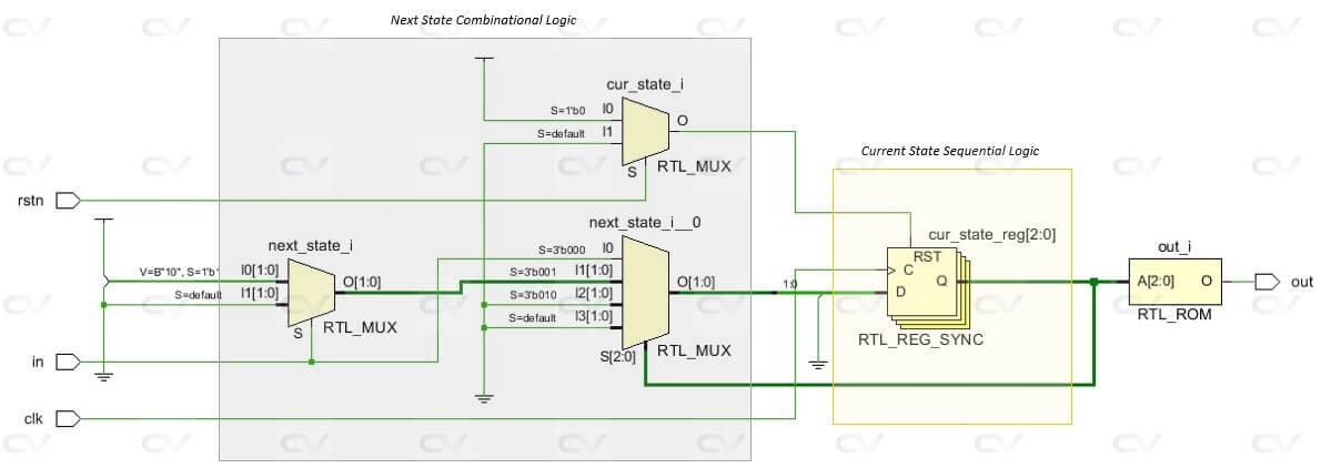
The two-always block method effectively partitions the Verilog code into its main functional blocks, mirroring the classical Finite State Machine (FSM) structure:
- Clocked Present State Logic
- Next State Combinational Logic
- Output Combinational Logic
This clear separation of concerns makes the two-always block method highly readable and maintainable, aligning well with the conceptual model of FSMs.
Click here for Pattern Detector Verilog FSM example !
